얼마전에 아니... 벌써 작년(^^)이 되었네요... 기구학 공부를 좀 혼자서 (취미로) 하면서 처음 잡았던 예제가 Two Link Planar에요.[바로가기] 그때 처음으로 정방향 기구학을 다루고 MATLAB으로 시뮬레이션을 했죠. 물론 그리고 나서 Processing으로 살짝 귀엽게 시뮬레이션을 했죠.[바로가기] 뭐 아무도 하라고 시킨 사람은 없지만 말이죠^^. 그리고 나서 당연한 수순이지만 역기구학을 또 공부했습니다.[바로가기] 이제 또 Processing으로 살짝 시뮬레이션을 할려고 헀지만... 회사 일이 바쁘고 해서 좀 미뤘다가 오늘 이렇게 포스팅을 하네요^^. 역기구학의 변환 결과만 살짝꿍 보죠^^

최초 이 그림을 쓸때 말씀드렸지만... 여전히 출처를 모릅니다.ㅠㅠ. 뭐 아무튼 저기서 목적은 끝단의 좌표를 알 때 역으로 두 각도를 알아서 그림을 그려주는 거죠^^


위 두 식이 두 각도를 구하는 결과식이었습니다. 당시에도 이야기를 했지만... Two Link Planar에서는 역기구학의 해법상 해가 두 개가 나타납니다^^. 이제 이걸 그려야죠^^ 저걸 그린 결과는

위 그림은 지난번에 그렸던 정기구학[바로가기]때와 같습니다. 그때는 아래에 있는 두 슬라이드바로 두 링크의 각도를 조절할 수 있었습니다.

끝 부분을 마우스로 잡고 움직이면 그 마우스 위치로 이동하기 위해 두 링크의 각도를 계산하는 것이죠. 뭐 그게 역기구학입니다만^^.ㅋㅋ
이제 살짝 코드를 들여다 보겠습니다. 어차피 전 아~주 임베디드한 사람이 아닌관계로 뭐 이따위로 코드를 짠거야?? 라고 욕하진 마세요... ^^. 그냥 저도 이것 저것 취미삼아 공부하는 거니까요^^
void draw() {
    background(255);

    drawPanel();

    if (isStartIKMode==1) {

        float[] tmp = calcInverseKinematics(mouseX - centerPos, centerPos - mouseY, a1, a2);

        if (previousState == 1) {
            if (tmp[1] > 0) {
                theta1 = tmp[0];
                theta2 = tmp[1];
            } else {
                theta1 = tmp[2];
                theta2 = tmp[3];
            }
        } else {
            if (tmp[1] < 0) {
                theta1 = tmp[0];
                theta2 = tmp[1];
            } else {
                theta1 = tmp[2];
                theta2 = tmp[3];
            }
        }

        drawBody(theta1, theta2);

    } else {

        drawBody(theta1, theta2);

        if (theta2 < 0) { previousState = -1; }
        else { previousState = 1; }

    }
}
Processing의 main문에 해당하는 draw함수인데요. 일단 기본 판넬을 그리는 drawPanel()이 있구요. 그리고 마우스로 기구의 끝단을 잡았는지 아닌지를 보고 현재 역기구학이 동작을 해야하는지 아닌지를 판단하는 if 문이 있습니다. 어차피 역기구학에서 동작을 해도 그림을 그릴려면 정기구학도 풀어야하기 때문에, 어차피 정기구학 해석 코드는 작동을 해야합니다. 그래서 역기구학을 풀어야하느냐 아니냐만 판정하는 거죠. 그리고 theta1,2를 이용해서 그림을 그리는 drawBody()함수가 있습니다. 단 이전에도 이야기했지만, 역기구학을 Two-Link Planar로 풀면 해가 두 세트가 될 때가 대부분입니다. 그래서 그려놓는거죠^^
void mousePressed() {
    if (mouseButton==LEFT) {
        if (abs(mouseX-(50+280)/2)<165 && abs(mouseY-550)<5) { grabSlider = 1; }
        if (abs(mouseX-(320+550)/2)<165 && abs(mouseY-550)<5) { grabSlider = 2; }
        if (isIKMode==1) { isStartIKMode = 1; }
        else { isStartIKMode = 0; }
    }
}

void mouseReleased() {
    if (mouseButton==LEFT) {
        grabSlider = 0;
        isIKMode = 0;
        isStartIKMode = 0;
    }
}
Procesing이 기본으로 제공하는 마우스가 눌러졌는지를 체크하는 함수인 mousePressed()와 눌러진 마우스가 풀어졌을때 실행할 후 있는 mouseReleased() 함수에 위와 같은 내용으로 코드가 들어간건데요. 일단 슬라이드위에서 마우스가 눌러지는 경우와 로봇의 끝단에서 마우스가 눌러지는 경우를 나눠서 grabSlider라는 변수로 구분을 짓습니다.^^.
void drawPanel() {
    fill(50);
    textFont(titleFont);
    text("Kinematics Example of Two Link Planar",140,25);
    textFont(smallFont);
    text("by PinkWink",500,45);

    stroke(150);
    line(50,550,280,550);
    line(320,550,550,550);

    if (grabSlider==1) {
        theta1 = (float(mouseX)-(50+280)/2)/115*PI;
    }

    if (grabSlider==2) {
        theta2 = (float(mouseX)-(320+550)/2)/115*PI;
    }

    slidePos1 = theta1*115/PI + (50+280)/2;
    slidePos2 = theta2*115/PI + (320+550)/2;

    stroke(100);
    fill(255);
    if (grabSlider==1) {fill(200);}
    ellipse(slidePos1,550,10,10);
    fill(255);
    if (grabSlider==2) {fill(200);}
    ellipse(slidePos2,550,10,10);
    fill(255);
    if (isStartIKMode==1) {
        fill(200);
        ellipse(mouseX, mouseY, 10, 10);
    }
}
drawPanel() 함수는 그냥 제목과 뭐 글자들을 찍는 함수인데요... 또 슬라이드를 그려야하기 때문에 조인트의 theta1,2를 이용해서 slidePos라는 슬라이드바의 위치를 계산해서 그리도록 하고 있습니다. 물론 fill() 명령으로 마우스로 잡았을때 색상을 살짝 바꾸도록도 하고 있구요^^
void drawObject(float[][] obTarget, float centerPos) {
    stroke(color(#000000));
    noFill();
    beginShape();
        vertex(centerPos + obTarget[0][0], centerPos - obTarget[1][0]);
        vertex(centerPos + obTarget[0][1], centerPos - obTarget[1][1]);
        vertex(centerPos + obTarget[0][2], centerPos - obTarget[1][2]);
    endShape(CLOSE);
}

void drawBodyAxis(float[][] bodyMat, float centerPos, float sizeOfAxis) {
    stroke(color(#FF0000));
    line(centerPos + bodyMat[0][3], centerPos - bodyMat[1][3],
        centerPos + bodyMat[0][3] + bodyMat[0][0]*sizeOfAxis,
        centerPos - (bodyMat[1][3] + bodyMat[1][0]*sizeOfAxis));

    stroke(color(#008000));
    line(centerPos + bodyMat[0][3], centerPos - bodyMat[1][3],
        centerPos + bodyMat[0][3] + bodyMat[0][1]*sizeOfAxis,
        centerPos - (bodyMat[1][3] + bodyMat[1][1]*sizeOfAxis));
}
그리고 drawBodyAxis()는 그냥 선만 딸랑 그려넣으면 재미없으니 x-y축을 표현해 넣는거구요. R-G-B 순으로 x-y-z축을 의미한다는 룰에 따라 x-y축만 표시를 합니다. 전체 창의 크기를 600*600으로 잡고 center를 300이라고 하면 거기부터 그려야하니 centerPos라는 말이 들어가 있어요^^ 그리고 drawObject는 위 그림에 보면 작은 삼각형이 하나 있는데요. 그냥 그린겁니다. (역시 심심할까봐^^) 그 아이를 그리는 거죠^^.
float[][] RotM(char axis, float theta) {
    if (axis=='a') {
        return new float[][]{{cos(theta),-sin(theta), 0,0},{sin(theta),cos(theta), 0,0},{0,0,1,0},{0,0,0,1}};
    } else if (axis=='o') {
        return new float[][]{{cos(theta),0,sin(theta),0},{0,1,0,0},{-sin(theta),0,cos(theta),0},{0,0,0,1}};
    } else {
        return new float[][]{{1,0,0,0},{0,cos(theta),-sin(theta),0},{0,sin(theta),cos(theta),0},{0,0,0,1}};
    }
}

float[][] TransM(float x, float y, float z) {
    return new float[][]{{1,0,0,x},{0,1,0,y},{0,0,1,z},{0,0,0,1}};
}
위 부분은 이전에도 이야기했던 정기구학을 위해 회전행렬(RotM)과 선형이동행렬(TransM)을 정의해 둔겁니다. x-y-z 순으로 a-o-n축으로 보고 회전행렬을 만든겁니다.^^
void detectEndEffector(float[][] endMat, float centerPos) {
    if ((abs(mouseX - (endMat[0][3]+centerPos)) < 10) && (abs(mouseY - (centerPos-endMat[1][3])) < 10)) {
        noFill();
        stroke(150);
        ellipse(centerPos + endMat[0][3], centerPos - endMat[1][3], 10, 10);
        isIKMode = 1;
    } else {
        isIKMode = 0;
    }
}
위 함수는 이름 그대로 현재 마우스가 기구의 끝에 위치해 있는지를 확입니다. 기구의 끝을 저장하는 것은 endMat이라는 행렬을 입력으로 주고, 마우스의 위치와 비교하구요. 살짝 10pixel 정도의 마진을 주고 있습니다. 그리고 마우스가 기구 끝에 위치하면 살짝 원하나 그려주는 것도 넣었구요^^
float[] calcInverseKinematics(float Px, float Py, float a1, float a2) {
    float th2_1 =  2*atan( sqrt( ( sq( a1 + a2) - ( sq(Px) + sq(Py) ) ) / ( sq(Px) + sq(Py) - sq( a1 - a2 ) ) ) );
    float th2_2 = -2*atan( sqrt( ( sq( a1 + a2) - ( sq(Px) + sq(Py) ) ) / ( sq(Px) + sq(Py) - sq( a1 - a2 ) ) ) );
    float th1_1 = atan2(Py, Px) - atan( a2*sin(th2_1) / ( a1 + a2*cos(th2_1) ) );
    float th1_2 = atan2(Py, Px) - atan( a2*sin(th2_2) / ( a1 + a2*cos(th2_2) ) );

    if ((Float.isNaN(th2_1))||(Float.isNaN(th2_2))||(Float.isNaN(th1_1))||(Float.isNaN(th1_2))) {
        textFont(smallFont);
        text("Unsolved Inverse Kinematics.", centerPos - 80, centerPos - 50);
        th1_1 = th1_2 = theta1;
        th2_1 = th2_2 = theta2;
    }

    return new float[]{th1_1, th2_1, th1_2, th2_2};
}
위가 바로 저번에 이야기한 역기구학을 푼것입니다.[바로가기] 주의할 점은 해가 두 개라는 거죠. 특별히 해가 없거나 혹은 두 각도가 모두 0도일때를 제외하면 대부분 다 해가 두 개입니다.^^. 특히 그 중에서 해가 없는 NaN인 상황을 만나면 유저에게 알려주기 위해 Processing에서 준비해준 Float.isNaN()함수를 사용해서 해 없는 상황을 체크하고 있습니다. 그리고 그 순간 그림은 계속 NaN 이전 상황이 유지되도록 하고 있구요^^.
void drawBody(float th1, float th2) {
    // calculation forward kinematics
    float[][] T_0_1 = Mat.multiply(RotM('a', th1), TransM(a1,0,0));
    float[][] T_1_2 = Mat.multiply(RotM('a', th2), TransM(a2,0,0));
    float[][] T_total = Mat.multiply(T_0_1, T_1_2);

    float[][] y0_1 = Mat.multiply(T_0_1, y0);
    float[][] y0_2 = Mat.multiply(T_total, y0);
    //

    float[] originX = { y0[0][3], y0_1[0][3], y0_2[0][3] };
    float[] originY = { y0[1][3], y0_1[1][3], y0_2[1][3] };

    // draw ellipse of joint
    noFill();
    stroke(200);
    ellipse(centerPos + y0[0][3], centerPos - y0[1][3], a1*2, a1*2);
    ellipse(centerPos + y0_1[0][3], centerPos - y0_1[1][3], a2*2, a2*2);

    // draw body lines
    strokeWeight(2);
    stroke(color(#8E8E8E));
    line(centerPos + originX[0], centerPos - originY[0], centerPos + originX[1], centerPos - originY[1]);
    line(centerPos + originX[1], centerPos - originY[1], centerPos + originX[2], centerPos - originY[2]);
    //

    // print angle of axis
    fill(50);
    textFont(tinyFont);
    text(nfs(theta1*180/PI,0,2), centerPos + originX[0], centerPos - originY[0] + 20);
    text(nfs(theta2*180/PI,0,2), centerPos + originX[1], centerPos - originY[1] + 20);
    String endPos = "( "+nfs(originX[2],0,2)+", "+nfs(originY[2],0,2)+" )";
    text(endPos, centerPos + originX[2]+20, centerPos - originY[2]+20);
    //

    drawBodyAxis(y0, centerPos, sizeOfAxis);
    drawBodyAxis(y0_1, centerPos, sizeOfAxis);
    drawBodyAxis(y0_2, centerPos, sizeOfAxis);

    float[][] pol0 = {{10,20,10},{10,10,20},{0,0,0},{1,1,1}};
    float[][] pol0_1 = Mat.multiply(T_0_1, pol0);
    float[][] pol0_2 = Mat.multiply(T_total, pol0);

    drawObject(pol0, centerPos);
    drawObject(pol0_1, centerPos);
    drawObject(pol0_2, centerPos);

    detectEndEffector(y0_2, centerPos);
}
위 코드는 정기구학을 Processing으로 그릴때도 사용했던 코드입니다.[바로가기] 일단 아무리 역기구학 시뮬레이터라도 그림을 그릴려면 정기구학을 사용해야하거든요. 그리고 마지막에 detectEndEffector() 함수로 항상 역기구학 상황인지를 체크하는 거죠^^. 허접한 Two Link Planar 시뮬레이터네요^^. 지금 계획은 이제 기구학에 대한 예제를 하나 더 할까하구요. 당연히 3D로 시뮬레이션을 하고 싶은데 말이죠... ㅎㅎ 3D는 그림 그리는데 좀 많은 공부를 필요로 하네요.^^. 아.. 전체 소스 코드는 Git[바로가기]에 있습니다.^^ 그리고 아래 그림은 동영상으로 결과를 보여드리는 거구요^^
이제 몇일 포근하더니 다시 추워질 모양입니다. 감기들 조심하세요^^
'Software > Processing' 카테고리의 다른 글
| 서보모터를 3D Builder를 통해 3D 도면의 좌표 중심을 변경하고 Processing에서 3D 도면을 표현하기 (6) | 2016.07.13 |
|---|---|
| 프로세싱 Processing에서 modelX 명령으로 pushMatrix의 개념을 이해하기... (2) | 2016.07.08 |
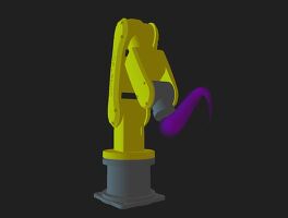
| Processing에서 구현해 보는 Robot Arm 소개 (6) | 2016.07.01 |
| Processing에서 Two Link Planar를 정방향 기구학으로 해석한 시뮬레이션 (12) | 2014.11.21 |
| Processing에서 Papaya library를 이용해서 행렬(Matrix) 연산하기 (22) | 2014.11.06 |
| Processing에서 진자 운동을 애니메이션으로 시뮬레이션하기 (17) | 2014.10.24 |
| Processing에서 시리얼통신으로 받은 데이터를 그래프로 표현하기 (32) | 2013.10.23 |